
 EN
EN
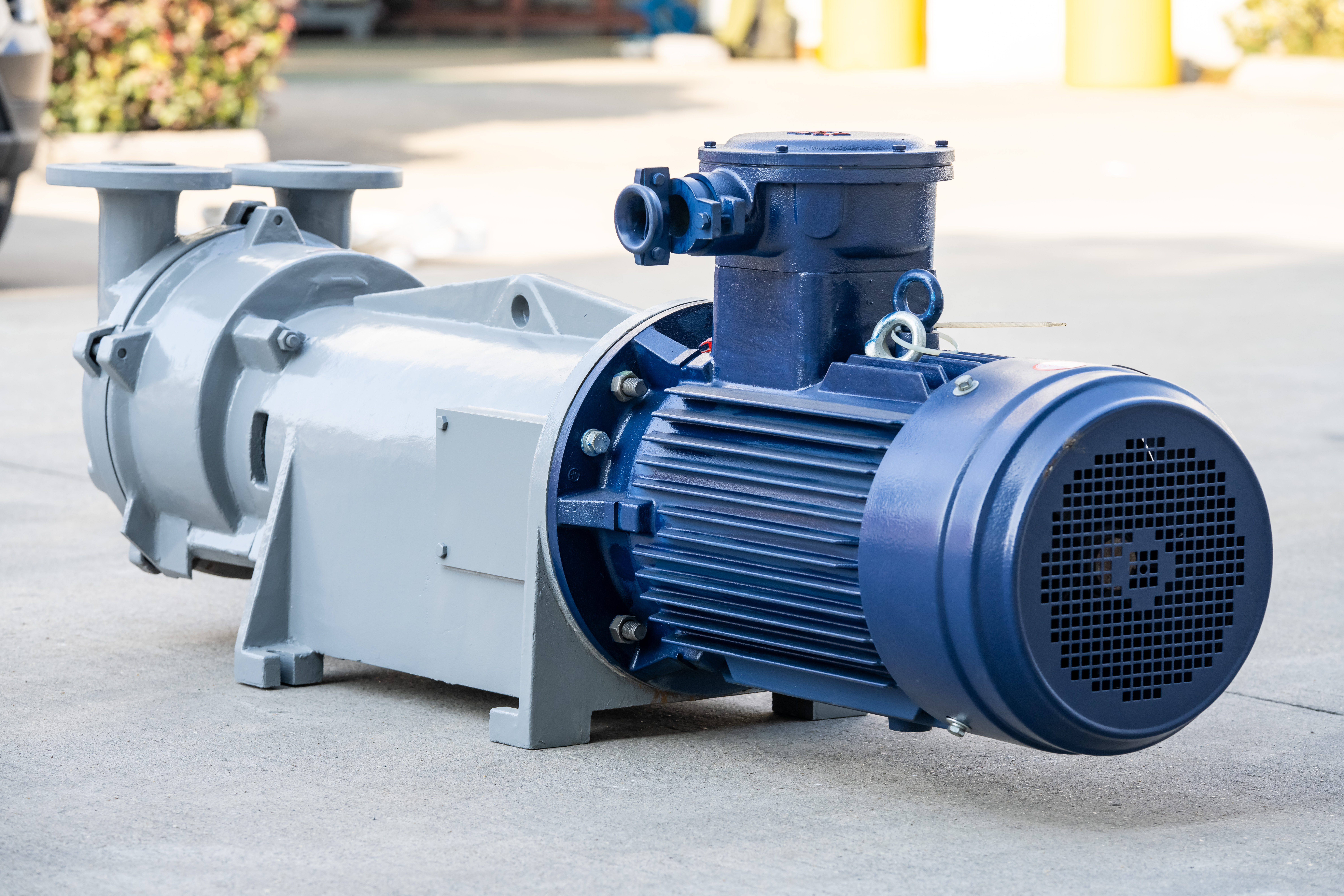
Understanding what determines the operational lifespan of a reciprocating vacuum pump is essential for engineers, maintenance planners, and procurement professionals who depend on consistent vacuum performance in industrial processes. Unlike rotary or centrifugal designs, the reciprocating vacuum pump relies on a precisely coordinated sequence of mechanical movements — pistons, valves, seals, and connecting rods working in concert under repeated stress cycles. Each of these components introduces a unique set of wear mechanisms that, when left unmanaged, can dramatically shorten service life and increase total cost of ownership.
The mechanical factors that affect reciprocating vacuum pump life are not arbitrary — they follow predictable engineering principles rooted in tribology, materials science, and thermodynamics. Identifying these factors early allows maintenance teams to design better service schedules, select appropriate lubricants and materials, and ultimately extend the working life of their vacuum equipment. This article examines the core mechanical variables that determine how long a reciprocating vacuum pump will perform reliably before requiring major overhaul or replacement.
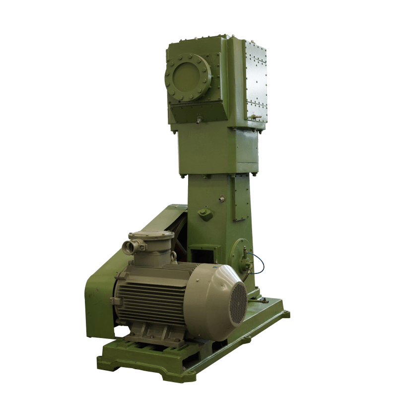
Piston and Cylinder Wear Dynamics
The Nature of Reciprocating Contact Stress
At the heart of every reciprocating vacuum pump is the piston-cylinder interface, where mechanical energy is converted into pressure differential. This interface experiences continuous reciprocating contact stress — a form of wear that differs fundamentally from rotational sliding wear. With every stroke, the piston exerts lateral forces on the cylinder wall due to connecting rod angularity, a phenomenon known as side thrust. Over thousands of operating hours, this lateral loading gradually wears the cylinder bore into an oval or tapered profile, reducing volumetric efficiency and increasing internal leakage.
The rate at which piston-cylinder wear accumulates depends on several interrelated factors: the surface finish of both mating components, the clearance tolerance specified during manufacture, the hardness of the materials used, and the effectiveness of the lubrication film maintained at the contact zone. In dry-running reciprocating vacuum pump designs, where oil lubrication is eliminated to prevent contamination, the piston ring material becomes especially critical. Self-lubricating composites such as PTFE-filled carbon or reinforced polymers are commonly used, but even these materials exhibit measurable wear under sustained operation.
Thermal expansion also plays a role in piston-cylinder wear. During warm-up cycles, differential thermal expansion between the piston and the cylinder can temporarily reduce running clearances, increasing friction loads. If the pump is frequently started and stopped — a condition common in batch processing environments — cumulative thermal cycling accelerates surface fatigue and micro-cracking, particularly at the top of the cylinder bore where combustion-like pressure peaks occur.
Piston Ring Integrity and Seal Degradation
Piston rings in a reciprocating vacuum pump serve a dual role: they maintain the pressure differential between the compression and suction sides while simultaneously transferring heat from the piston to the cylinder wall. When piston rings lose tension, develop radial cracks, or experience extrusion into the ring groove, both sealing integrity and thermal management are compromised simultaneously. The vacuum attainment level drops noticeably, and thermal hot spots may develop on the piston crown.
Ring groove wear is a subtler failure mode that often goes undetected until vacuum performance has significantly degraded. As the groove widens due to cyclic impact loading, rings begin to rock axially rather than maintaining a steady seating contact. This rocking motion accelerates ring face wear, generates fine metallic debris, and can cause localized scoring of the cylinder bore. Regular inspection of ring groove clearance — both radial and axial — is therefore a key diagnostic step in any preventive maintenance program for a reciprocating vacuum pump.
Valve Mechanism Wear and Fatigue
Reed Valve and Plate Valve Stress Cycles
The valve system is arguably the most mechanically demanding component group in any reciprocating vacuum pump. Whether the design uses reed valves, plate valves, or poppet valves, each valve must open and close with every piston stroke — potentially thousands of times per hour. This cyclic mechanical fatigue is the primary cause of valve failure and is responsible for a disproportionately large share of unplanned reciprocating vacuum pump downtime across industrial applications.
Reed valves are especially susceptible to fatigue cracking because they function as cantilever beams under repeated bending stress. The stress amplitude at the valve root is a function of the pressure differential, the valve stiffness, and the frequency of operation. Higher vacuum depths increase differential pressure and therefore increase the bending moment at the root. Operators running a reciprocating vacuum pump at or near its maximum vacuum rating continuously will observe significantly shorter valve life compared to those operating the unit at moderate vacuum levels.
Valve seat condition is equally important. Even a minor nick, erosion pit, or carbon deposit on the valve seat prevents full sealing between strokes, allowing backflow that reduces effective displacement and forces the pump to work harder to achieve the target vacuum. This additional load increases piston forces, heats the gas, and accelerates wear across multiple components simultaneously. Valve seat maintenance is therefore a cascade-effect intervention — repairing the seat improves conditions throughout the entire reciprocating vacuum pump mechanism.
Impact Loading and Valve Bounce
At high operating speeds, valve bounce becomes a significant mechanical concern. When a valve closes rapidly at the end of its stroke, elastic rebound can cause it to lift momentarily off its seat before settling. This bounce allows a small quantity of compressed gas to escape backward through the valve, reducing efficiency. More critically, repeated impact loading at high velocity accelerates fatigue damage to both the valve plate and its seat, compressing the useful service interval considerably.
Engineers designing or selecting a reciprocating vacuum pump for high-speed applications must carefully evaluate valve geometry and spring characteristics to minimize bounce. Excessive valve lift — which increases flow capacity in theory — can actually reduce service life in practice by allowing higher impact velocities when the valve closes. Matching valve design to the actual operating speed and vacuum range is therefore a critical factor in maximizing pump longevity.
Bearing Load and Crankshaft Fatigue
Dynamic Load Cycles on Main Bearings
The crankshaft and connecting rod bearings of a reciprocating vacuum pump experience dynamic loads that vary significantly throughout each rotation. During the compression stroke, gas pressure forces push back against the piston, transmitting substantial tensile and compressive loads through the connecting rod to the crankpin bearing. During the suction stroke, inertia loads dominate. This alternating load reversal is more damaging to bearing films than unidirectional loads, because it periodically squeezes out the lubricant wedge that normally provides hydrodynamic separation.
Bearing wear rate in a reciprocating vacuum pump is strongly influenced by operating speed, oil viscosity, oil cleanliness, and bearing clearance. When oil viscosity drops due to elevated temperature or contamination, the minimum film thickness decreases, and metal-to-metal contact becomes more frequent during load reversals. Over time, this produces bearing surface fatigue in the form of spalling, wiping, or fretting — each of which generates abrasive debris that accelerates the wear of downstream components.
Crankshaft fatigue is a related concern, particularly in reciprocating vacuum pump designs that operate at high stroke frequencies or handle large displacement volumes. Stress concentrations at fillet radii, oil holes, and cross-bore intersections in the crankshaft can initiate fatigue cracks under cyclic bending and torsional loading. Careful design with generous fillet radii and shot-peened surfaces can significantly extend crankshaft fatigue life, but operating the pump beyond its rated speed or pressure range will override these design margins.
Connecting Rod and Wrist Pin Wear
The connecting rod small-end bearing — also called the wrist pin or gudgeon pin bearing — experiences some of the highest specific loads in the entire reciprocating vacuum pump mechanism. Because this bearing oscillates rather than rotating continuously, it cannot generate a full hydrodynamic film and relies more heavily on boundary lubrication. Wear at the wrist pin bearing is therefore often more pronounced than at the main bearings, even when overall lubrication conditions are adequate.
Clearance control at the wrist pin is critical. Excessive clearance allows impact loading on each stroke reversal, generating audible knock and accelerating both the pin and the connecting rod bore. Insufficient clearance can cause seizure during thermal expansion under load. Maintaining the manufacturer's specified wrist pin clearance through regular inspection and timely component replacement is one of the most effective ways to preserve long-term reciprocating vacuum pump reliability.
Lubrication System Performance and Its Mechanical Consequences
Oil Film Degradation and Its Effect on Wear Rates
For lubricated reciprocating vacuum pump models, the condition of the lubricating oil is arguably the single most influential factor in determining component wear rates. Oil degrades through thermal oxidation, contamination with process vapors, particulate ingestion, and the progressive accumulation of metallic wear debris. As the oil's viscosity index, oxidation stability, and anti-wear additive package degrade, the protective film thickness at critical interfaces decreases, and wear accelerates nonlinearly.
Process vapor condensation inside the crankcase is a particularly aggressive form of oil contamination in vacuum applications. When the pump handles humid gases or solvents, condensate can accumulate in the oil sump, causing emulsification and corrosive attack on bearing surfaces. This type of contamination is not always visible as a change in oil color, making regular oil analysis — including water content, acid number, and viscosity measurements — essential for any reciprocating vacuum pump operating in demanding process environments.
The lubrication delivery system itself — the oil pump, galleries, and splash rings — must also be kept in good working order. A partially blocked oil gallery or a worn oil pump can create localized starvation at critical bearings, causing rapid wear even when the bulk oil condition is acceptable. Pressure drop measurements across the oil circuit and regular inspection of oil strainers are straightforward maintenance steps that pay significant dividends in reciprocating vacuum pump longevity.
Dry-Running Design Considerations for Oil-Free Models
In dry-running or oil-free reciprocating vacuum pump configurations, the lubrication challenge is addressed through material selection rather than oil delivery. Self-lubricating piston rings, guide bands, and valve plates made from advanced polymer composites transfer microscopic amounts of solid lubricant to the mating surface during operation, creating a thin transfer film that reduces friction and wear. The longevity of this transfer film — and therefore the service life of the pump — depends on operating conditions including temperature, speed, and gas cleanliness.
Contaminated intake gas is a major threat to dry-running reciprocating vacuum pump components. Abrasive particles strip the transfer film faster than it can be replenished, leading to accelerated polymer ring wear and potential scoring of the hard-coated cylinder bores. Installing properly rated inlet filtration, monitoring filter differential pressure, and replacing filter elements on schedule are critical maintenance practices that directly protect the mechanical life of oil-free pump designs.
Thermal Management and Its Role in Mechanical Longevity
Heat Generation Patterns in Reciprocating Operation
Thermal loading is an often underestimated mechanical factor in reciprocating vacuum pump life. During compression, gas temperature rises according to thermodynamic principles, and this heat must be dissipated through the cylinder walls, piston, and ultimately through the cooling system. When heat dissipation is inadequate — due to fouled cooling fins, blocked coolant passages, or ambient temperature extremes — elevated component temperatures accelerate multiple wear mechanisms simultaneously: oil oxidation, polymer seal degradation, differential thermal expansion, and material fatigue.
Air-cooled reciprocating vacuum pump designs are particularly sensitive to ambient temperature and airflow conditions. Restricted airflow around the pump — caused by inadequate ventilation in the installation environment, dust accumulation on cooling fins, or improper enclosure design — can raise cylinder head temperatures significantly above design limits. Monitoring discharge temperature as a routine operating parameter provides an early warning of thermal management problems before they escalate into component damage.
Thermal Cycling and Component Fatigue
Frequent start-stop operation subjects a reciprocating vacuum pump to repeated thermal cycling — cycles of heating during operation and cooling during downtime. Each thermal cycle induces differential expansion and contraction between components of different materials and geometries, generating low-cycle thermal fatigue stresses. Valve plates, cylinder heads, and gasket interfaces are especially vulnerable to this type of damage, which manifests as cracking, distortion, or gasket failure after a relatively small number of operating hours compared to continuously running units.
Designing an operating schedule that minimizes unnecessary start-stop cycles — using variable speed drives or unloading valves to maintain the pump in a standby state rather than cycling power — is a practical strategy to reduce thermal fatigue and extend the mechanical life of a reciprocating vacuum pump. This is particularly relevant in applications where vacuum demand is intermittent or highly variable throughout the production shift.
FAQ
What is the most common cause of premature reciprocating vacuum pump failure?
Valve failure is statistically the most common cause of premature reciprocating vacuum pump failure in industrial settings. Cyclic mechanical fatigue at the valve root, combined with impact loading from high-speed operation and seat erosion from contaminated gas streams, causes valves to crack, distort, or lose seating integrity. This leads to internal leakage, reduced vacuum performance, and increased thermal loading across the entire pump mechanism. Regular valve inspection and replacement at manufacturer-recommended intervals is the most effective single maintenance action to prevent this failure mode.
How does operating vacuum depth affect reciprocating vacuum pump component life?
Operating a reciprocating vacuum pump at deeper vacuum levels increases the differential pressure across both valves and piston rings, amplifying the mechanical stresses on these components. Valve bending stresses increase directly with differential pressure, accelerating fatigue cracking. Piston ring sealing loads increase, raising friction and wear rates at the ring-cylinder interface. Bearing loads also increase because higher gas forces are transmitted through the connecting rod. For applications where the full rated vacuum depth is not continuously required, operating at a moderate vacuum level and using a control valve to regulate the process vacuum can significantly extend component life.
Does operating speed significantly affect the lifespan of a reciprocating vacuum pump?
Yes, operating speed has a substantial impact on reciprocating vacuum pump lifespan. Higher speeds increase the frequency of valve opening and closing cycles, directly proportionally increasing valve fatigue damage accumulation. They also raise inertia loads on connecting rod and wrist pin bearings, increase hydrodynamic film demands on all lubricated interfaces, and generate more heat per unit time. Many manufacturers publish speed derating guidelines that recommend reduced maintenance intervals or reduced duty cycles when operating near the upper end of the rated speed range. Following these guidelines is an important step in preserving pump longevity.
How can inlet filtration improve the mechanical life of a reciprocating vacuum pump?
Proper inlet filtration removes abrasive particulates from the gas stream before they can enter the compression chamber of a reciprocating vacuum pump. In oil-free designs, abrasive particles destroy the self-lubricating transfer film on polymer rings and valve plates, rapidly accelerating wear. In lubricated designs, particles entering via the inlet can contaminate the oil, dramatically increasing bearing and cylinder wear rates. Selecting an inlet filter with the appropriate micron rating for the application, monitoring differential pressure across the filter, and replacing filter elements on schedule are straightforward practices that yield measurable improvements in pump mechanical life and reliability.
Table of Contents
- Piston and Cylinder Wear Dynamics
- Valve Mechanism Wear and Fatigue
- Bearing Load and Crankshaft Fatigue
- Lubrication System Performance and Its Mechanical Consequences
- Thermal Management and Its Role in Mechanical Longevity
-
FAQ
- What is the most common cause of premature reciprocating vacuum pump failure?
- How does operating vacuum depth affect reciprocating vacuum pump component life?
- Does operating speed significantly affect the lifespan of a reciprocating vacuum pump?
- How can inlet filtration improve the mechanical life of a reciprocating vacuum pump?